Machining
Subtractive work: a tool cuts material away until the part is what’s left. Milling is one kind of machining. Turning, drilling, grinding, and EDM are other ways to remove metal. “Machine it” does not always mean “put it on a mill.”
Shop words in plain language, plus a classic 707 airframe glossary. A memory aid, not a drawing and not the standard.
Nothing matches that. Try a shorter word, or a shop nickname like “jiggle” (the term is joggle).
How metal becomes a part, and which shop actually does which step.
Subtractive work: a tool cuts material away until the part is what’s left. Milling is one kind of machining. Turning, drilling, grinding, and EDM are other ways to remove metal. “Machine it” does not always mean “put it on a mill.”
A spinning cutter moves across a part that is clamped still (or the table moves the part under the cutter). Typical work is faces, pockets, slots, and contours. On a vertical mill the tool points down.
Example: facing the top of a plate, then pocketing a recess, is milling. Turning that same plate into a round shaft is not.
The workpiece spins and a tool that does not spin feeds into it. Used for diameters, faces, grooves, and threads on round parts. The machine is a lathe, not a mill.
A drill opens a hole. That hole is a starting size and location, not a finished precise bore. Drilling can happen on a mill, a lathe, or a drill press.
An abrasive wheel rubs off a little material for a fine surface or a tight size, often after cutting. It is still subtractive, but it is not a milling cutter.
Electrical discharge machining. Sparks erode conductive metal instead of a cutting edge shearing it. Wire EDM cuts a path through the part with a thin wire. Sinker (ram) EDM pushes a shaped electrode in to burn a cavity.
Example: a sharp inside corner a round end mill cannot reach, or a feature in metal that is already very hard, is a common reason to EDM.
Stock that already has a simple cross-section: flat plate, round bar, or rectangular bar, cut to a length you can fixture. You buy the shape; you do not forge it in the machine shop.
A solid chunk of wrought metal a shop cuts the part from, usually sawed from bar or plate. “Billet” names the starting piece, not a special alloy and not a forging.
Melt the metal, cast an ingot, hot-work it (roll, extrude, or forge) so the structure closes up and stretches, then cut that long product to the length the shop needs. The machine shop usually receives the piece after all of that.
Hot metal is pressed or hammered into a shape closer to the finished part. Grain is pushed to follow that shape. Forging is a forming step, not machining.
Molten metal is poured into a mold. The grain is not stretched the way it is in rolled bar or a forging, so strength and machining behavior are different even when the alloy name looks similar.
Metal is pushed through a die so the cross-section stays the same along the length: tube, angle, or a custom profile. Grain runs along that length.
A common chain is billet, then forge, then machine: the forge makes the near-net shape, and a machine shop cuts the precise faces, holes, and fits. Plenty of shops only machine. They fixture plate, bar, or billet and never see a hammer.
In wrought metal, grain follows the direction the metal was stretched while hot. On bar that is the long axis. On a forging, the drawing may show grain-flow arrows that bend with the shape. Do not guess from the silhouette. Use the drawing or the material certification.
How many directions the machine can move, and the questions that pick a process.
The tool moves in X, Y, and Z. On a typical vertical mill the spindle stays pointing down. The other side of the part is a new clamp: you flip it.
Adds rotation about one axis, usually called A (rotation about X). You can index the part to a new side, and on some jobs rotate it while cutting. The usual reason is a feature that wraps a side, or several sides that must stay on one datum setup.
Adds a second rotary (often B about Y, or C about Z, depending on the machine). The name alone does not say whether those rotaries move during the cut. Ask whether the job is 3+2 or simultaneous.
The two rotary axes tilt the part or the head to a fixed angle and lock. Cutting after that is ordinary 3-axis. This reaches compound angles without all five axes moving at once.
X, Y, Z and both rotaries move while the cutter is in the metal. That is what sculpted surfaces, some undercuts, and a tool axis that must keep changing actually need. A machine that can do it is not required to do it on every part.
Can a vertical tool reach every face if you flip the part? Then 3-axis plus fixtures is enough.
Do features wrap around, or must several sides stay in one fixture so datums do not stack from setup to setup? Then a rotary (4-axis or 3+2) earns its keep.
Are there compound angles or undercuts a vertical tool still cannot see after a flip? Then 3+2 or simultaneous 5-axis.
Mill-turn machines, robots, and pallet indexers are often a process choice, not a new geometric axis. They change how the part is held, turned, or swapped. They do not automatically mean the cutter can reach a shape a 5-axis mill could not.
Usually 3-axis with a flip between two fixtures (or two ops), not a 4-axis program. Move to a rotary when side features wrap, or when the datums are tight enough that both sides should be cut in one clamping.
What is inside a typical C-frame vertical machining center (VMC), and which parts actually move. Generic layout; real machines differ in where the motors, tank, and tool changer sit.
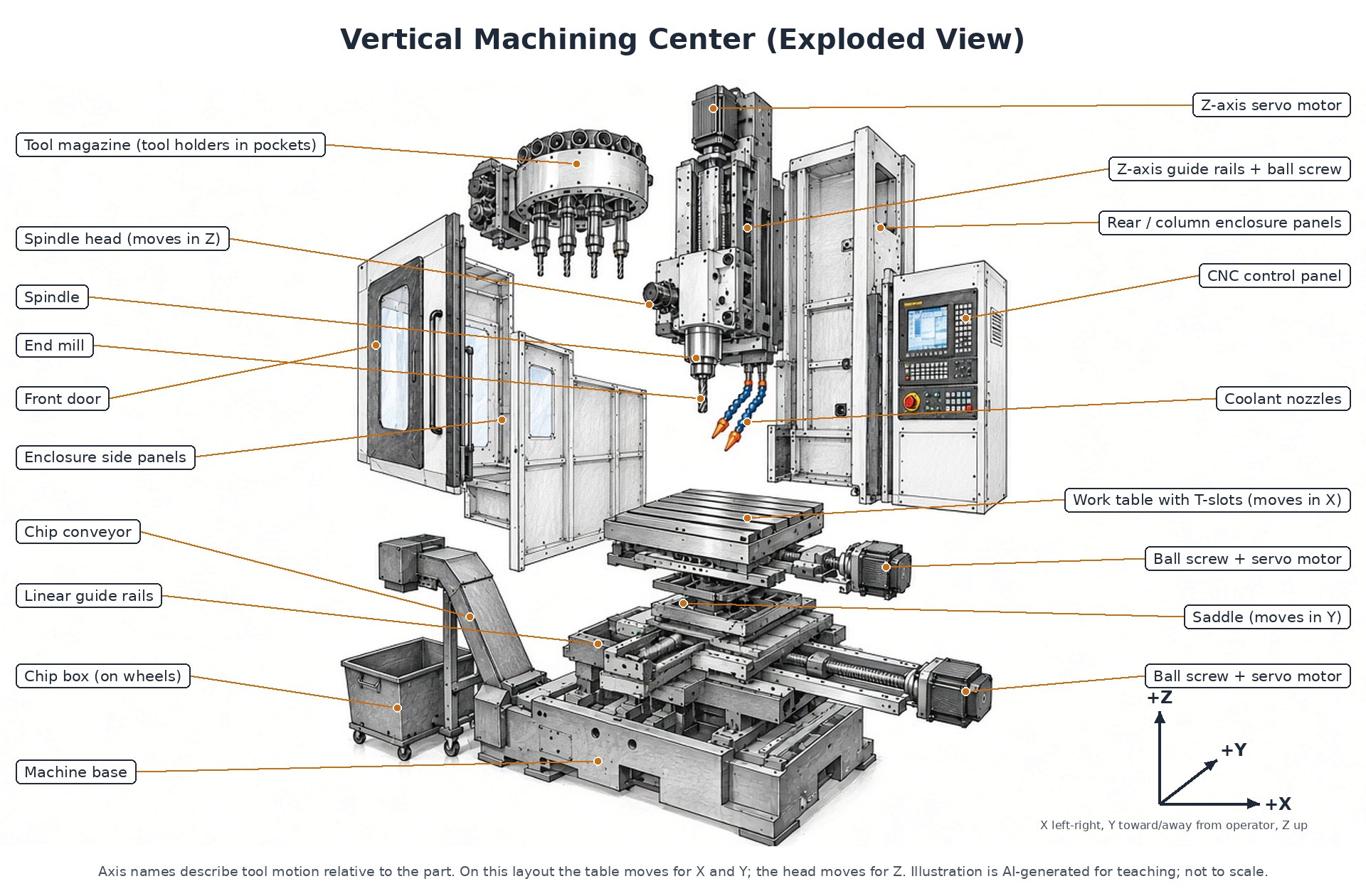
Numbered schematic
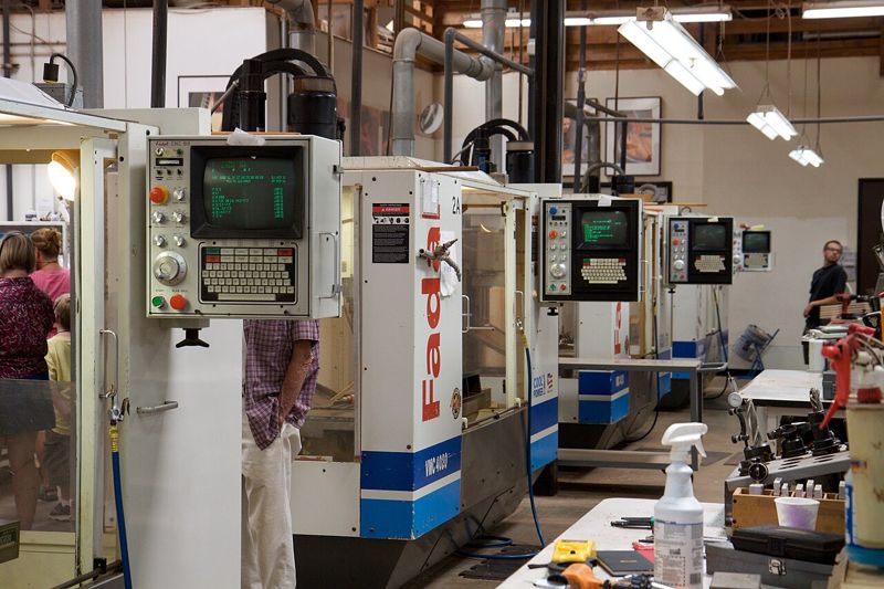
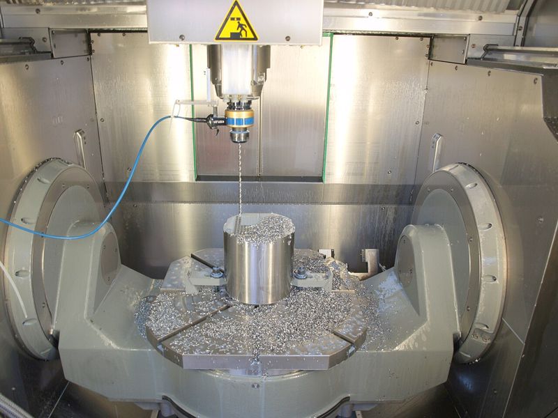
Structure and motion
The heavy bottom casting, usually cast iron, that everything else sits on. Its mass and stiffness soak up vibration. It carries the Y rails and the column, and stands on leveling feet.
Some machines use a polymer-concrete (mineral) base for extra damping. A machine that is not level and settled will not hold accuracy, however good the parts on top are.
The fixed upright at the back of the base. It carries the Z rails, the Z ball screw, and the spindle head. On a C-frame VMC it never moves.
Seen from the side, base plus column makes the “C” shape: cutting forces try to open the C, so a stiffer column means a heavier cut is possible.
The carriage between the base and the table. It rides the base rails front to back (Y) and carries the X rails on top.
The top of the motion stack. It rides the saddle left and right (X) and has T-slots for T-nuts, so vises, fixture plates, and clamps can be bolted down. See T-slot and the workholding cards.
On this layout a +X move makes the table go left, so the tool moves right relative to the part. The program describes tool motion; the machine sorts out which casting moves.
Linear guides are hardened rails with bearing blocks (trucks) full of rolling balls or rollers: low friction, fast rapids, little wear. Box ways are wide sliding surfaces, scraped and lined with a low-friction material: more contact area and damping for heavy cuts, but slower and more friction.
Most new VMCs use linear guides. Box ways are still found on machines built for heavy cutting in hard materials.
A screw whose nut rolls on recirculating balls instead of sliding, turning motor rotation into straight motion with very little friction and almost no backlash. There is one per linear axis. The nut is preloaded so it does not rattle back and forth when the direction reverses.
Not the same as a plain lead screw on an old manual mill, which slides and has backlash you can feel at the handwheel.
Each axis has a servo motor driving its ball screw. An encoder on the motor reports exactly how far it has turned, and the drive keeps correcting until the axis is where the control asked. That is closed-loop control.
Some machines add linear scales on the axis itself, so position is measured at the table instead of being worked out from motor turns.
The housing that carries the spindle and its motor. It rides the column rails up and down (Z). Its weight is often balanced by a counterweight, gas springs, or a brake on the Z motor so it does not drop when power is off.
Telescoping steel covers, and folding accordion bellows on some axes, that shield the rails and ball screws from chips and coolant while the axes move.
A dented or torn cover lets chips into the guides and screws. Report it rather than running it.
An automatic lubricator that pumps small amounts of oil or grease to the rails and ball screws on a timer. It has its own reservoir, and the control alarms when it runs low.
Spindle and tool change
The rotating shaft that holds the tool holder in its taper. A belt-drive spindle has its motor alongside, driving through belts. An inline (direct-drive) spindle has the motor on top, coupled straight to the shaft. A built-in (motorized) spindle has the motor inside the spindle housing itself.
Belts and gear ranges give more torque at low RPM; inline and built-in spindles reach higher RPM more smoothly. The taper itself (CAT40, BT40, HSK) is under Spindle taper.
The spindle shaft runs in precision preloaded bearings inside a cartridge (the housing). Those bearings set how true the tool runs and how much side load the spindle can take.
A spindle warm-up program brings the bearings up to temperature gently after the machine sits. A crash can damage the bearings even when nothing looks broken; check runout afterward.
The rod inside the spindle that grabs the holder’s pull stud and pulls the holder up into the taper. A stack of disc springs holds it clamped; a hydraulic or air cylinder compresses the springs to release the tool.
The tool release button fires that cylinder, so hold the tool before pressing it. Air blown through the spindle during a change cleans chips off the taper.
An umbrella or carousel changer is a ring of tool pockets that swings or slides to the spindle and swaps the tool directly, with no arm. A side-mount changer keeps the magazine beside the column, often a disk or chain, and a double-ended arm grabs the old and new tools at once and swaps them in a fraction of the time.
The magazine is the storage; the changer is the mechanism. The pocket and T-number bookkeeping is under ATC and tool pocket.
A spindle probe usually lives in a magazine pocket and is loaded like a tool. A tool setter is bolted to a corner of the table where it will not interfere with the work. See Spindle probe and Tool setter vs presetter.
Control, enclosure, and power
The CNC control is the computer and drives that run the program. The pendant is the operator panel on its arm: screen, keypad, cycle start, feed hold, overrides, and the emergency stop.
Feed hold pauses the axes; the e-stop cuts power to motion and is for emergencies. See Feed and speed override.
Manual pulse generator: a knob that jogs the selected axis a fixed step per click, for example 0.0001, 0.001, or 0.01 in. Used to touch off, indicate, and move carefully near the part. Many are on a cord so you can stand at the work.
Check which axis and which step size are selected before you turn it. A wrong step size is how a slow jog becomes a crash.
The cabinet, usually at the back, holding the servo and spindle drives, power supplies, relays, and the machine’s logic controller. An air conditioner or heat exchanger keeps it cool and clean.
Keep the door shut so coolant mist and dust stay out. It has dangerous voltage inside, even with the machine stopped; it is a job for maintenance.
The sheet-metal housing that keeps chips and coolant in. The front door has a safety window and an interlock; with the door open, most machines stop or tightly limit spindle speed and axis motion.
The light inside the enclosure, usually LED, that lets you see the part and the tool through the window.
Coolant and chips
The tank (sump) beside or under the machine that holds the coolant, with the pump that sends it to the nozzles and screens that keep chips out of the pump.
Water-based coolant concentration is checked with a refractometer. Oil floating on top (tramp oil, mostly way lube) should be skimmed off.
Adjustable segmented or ring nozzles around the spindle that aim flood coolant at the cut. Some machines aim a nozzle automatically from the tool length.
Re-aim them after a long or short tool change; coolant hitting the holder instead of the cut does little.
An extra high-pressure pump and fine filter feed coolant through a rotating seal at the top of the spindle and down through the holder and tool. The use is described under Coolant.
A chip auger is a screw in a trough in the base that pushes chips toward the outlet. A chip conveyor lifts chips out of the machine and drops them in a bin: a hinged-belt conveyor suits long, stringy chips; a scraper or drag type suits fine chips such as cast iron or small aluminum chips.
The bin at the end of the conveyor. Empty it before it overflows and backs chips up into the conveyor.
Other layouts
A VMC’s spindle points down. A horizontal machining center (HMC) points its spindle sideways at a part that usually sits on a rotary pallet. Chips fall away from the cut, and a pallet changer lets one part load while another is machined.
HMCs are where tombstones and indexed sides really pay off.
A C-frame has one column at the back, and the table moves under the spindle. A bridge (double-column) machine carries the head on a beam spanning two columns, which is stiffer for wide parts. A gantry moves that beam over a fixed table, so very long or heavy parts never have to move.
Long aerospace parts such as spars and skin panels are often machined on gantry or large moving-column machines.
A column-and-knee layout. The table moves in X on a lead screw turned by a handwheel, and the saddle under it moves in Y on the cross-feed screw. The knee carries both and cranks up and down on the column to set table height. The quill feeds the spindle down out of the head for drilling. On top, the head holds the motor, belts, and pulleys (or a variable-speed drive), and the ram lets the head slide in and out and swivel. Most now have a digital readout (DRO) on the axes.
In aerospace it is not a production machine; that work is on CNC VMCs, HMCs, and 5-axis machines. Knee mills are still common in toolrooms and maintenance shops for one-off parts, fixture changes, prototypes, and training.
The plus directions describe the tool moving relative to the part. +Z is away from the work, so up on a VMC. Facing the machine, +X is the tool moving to the right and +Y is the tool moving toward the column.
On a moving-table VMC the table goes the opposite way: +X slides the table left, and +Y brings it toward you. See Axes.
A fixture trick for a rotary table. The cutting is still 3-axis.
A tall fixture block stood on a rotary indexer, with parts clamped on the vertical faces. The indexer turns from face to face. The spindle still cuts with three linear axes; the rotation is indexing, not a sculpted 5-axis toolpath.
Each face can hold more than one part. One index cycle then machines a batch before the tombstone turns to the next face.
A second pallet, often a second tombstone, sits outside the cutting zone. You load and unload that one while the machine cuts the first. The spindle does not wait on clamping.
Names you will hear at the machine and see in a program or on a print.
A cut that makes a flat surface, usually the top of the stock, so later features have a clean height to start from.
A cavity with a floor, closed or mostly closed on the sides. The tool steps down and clears the area, then finishes the walls and floor.
Example: a rectangular recess that a cover sits in.
A long, narrow channel. Often open at one or both ends. A slot is a shape; a keyway is a slot with a job.
A slot that holds a key so a shaft and a hub turn together instead of spinning on each other.
Example: a groove along a shaft, sized for a square key.
The cutter follows an outline, inside or outside, instead of clearing a whole area. On a drawing, “profile” can also mean a GD&T control. In a program it usually means this toolpath.
A raised pad left standing above the surrounding face. Often a place for a bolt, a bearing, or a seal to sit.
A flat bevel on an edge, often 45°. It knocks off a sharp corner or gives a screw a lead-in.
A rounded corner. An inside fillet is what a round end mill leaves in a pocket corner; you cannot get a perfectly sharp inside corner with that tool.
A shallow flat circle around a hole so a bolt head or washer sits square. Only deep enough to clean the surface, not deep enough to hide the head.
A larger flat-bottomed diameter above a smaller hole, deep enough that a socket-head cap screw can sit below the surface.
A cone-shaped recess so a flat-head screw sits flush. The angle matches the screw, often 82° or 90°.
Enlarge a hole that already exists, with a boring bar or boring head, so size, roundness, and location are better than a drill alone can hold.
A reamer follows a hole that is already there and finishes the diameter. It improves size and finish. It does not move the hole to a new location in any useful way.
An internal thread cut by a tap (or a single-point tool on a lathe). The tap’s shape is the thread. If a tap breaks, it is stuck in the hole.
A spinning cutter that orbits the hole (or a boss) in a helix and mills the thread. One cutter can cover a range of diameters. A broken thread mill usually comes out; it is not wedged like a tap.
The tool: a single-profile thread mill has one tooth form and works its way along the thread; a multi-form one has several rows of teeth and cuts the full length in about one orbit. Solid carbide is typical. The pitch must match the thread; the diameter does not. More tools under CNC tooling.
Heavier cuts that get close and leave extra metal on purpose. Speed of removal matters more than the final surface.
Lighter cuts that bring the surface to final size and the required finish. Often a separate tool or a separate pass after roughing.
How far the tool drops in Z between passes. A smaller stepdown is easier on the tool and usually leaves a better wall.
Also called depth of cut (DOC), axial depth, or ap. Adaptive roughing flips the usual habit: a deep DOC using most of the flute, with a small WOC. See CNC tooling.
How far the tool steps sideways between passes. A smaller stepover leaves a smoother floor and takes longer.
In roughing the same idea is called width of cut (WOC), radial engagement, or ae, often given as a percent of tool diameter. A full-width slot is 100% WOC, the hardest cut on a tool.
Metal the toolpath is told to leave behind so a later finish pass, or another setup, can clean it up. Roughing with zero stock to leave is how you scrap a face early.
Material that hangs over a feature so a straight vertical tool cannot reach it. You need a tilted axis, a special cutter (lollipop, T-slot, dovetail), or EDM.
A thin rim or ledge standing off a wall or around an opening. Often a seal land, a weld lip, or a bolt flange.
A slot or rail that is wider at the bottom than at the opening, so the mating slide cannot lift straight out. Cut with a dovetail cutter or by tilting the tool.
A slot shaped like an upside-down T. A T-nut slides in and clamps fixtures. Machine tables are full of them. Cut with a T-slot cutter after a narrow slot is already open.
A groove sized so an O-ring sits in it and compresses when the joint closes. Width, depth, and surface finish matter more than a cosmetic radius. Use the groove the seal maker specifies, not a guess.
Extra room cut so something else has clearance: a tool, a mating corner, or the end of a thread.
Example: a small groove at the end of a thread so the full thread can finish instead of fading into a shoulder.
A short offset step in a flange, sheet, or extrusion so two overlapping pieces can sit flush. It is a real shop word. It is not “jiggle.”
Example: a flange steps sideways by about one material thickness, then continues, so the joint does not stack two thicknesses.
A theoretically exact plane, axis, or point the drawing measures from. Real surfaces are chosen to stand in for those datums. Features are located from the datums, not from whichever edge happened to be handy.
A fixture holds the part in a known place and orientation. A jig, strictly, also guides the tool. On a CNC mill people often say fixture for the whole workholding setup.
An op (operation) is one block of work, often one clamping. A setup is getting the part located and the tools ready before that op runs. Flipping the part to cut the back is a new setup even if it is the same machine.
Where a feature is supposed to be, exactly, from the datums. The GD&T position tolerance is a zone around that true spot. See Position under GD&T for how to read the frame.
Cutters, holders, workholding, and the speed and feed words that go with them on a CNC mill. Names are generic. The tool maker’s data and your shop’s numbers beat anything written here.
Already on this page, so not repeated here: Thread mill, Stepover (WOC), and Stepdown (DOC) under Cuts and features; the Tombstone; 4-axis and 5-axis; and Spindle / tool runout. Photos are free Wikimedia Commons files saved on this site, credited under each one. The sketches are original.
Milling cutters
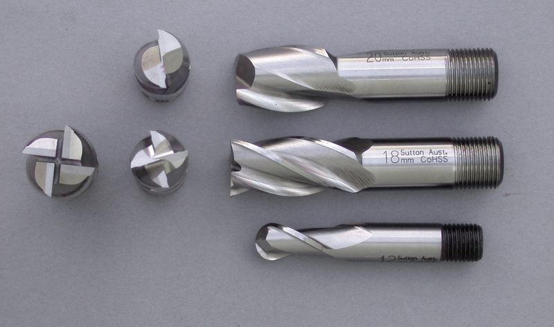
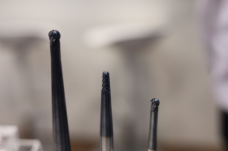
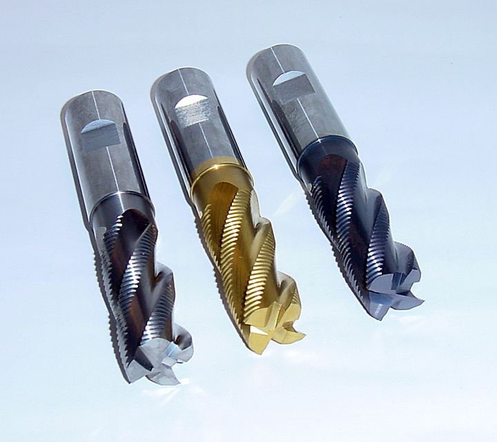
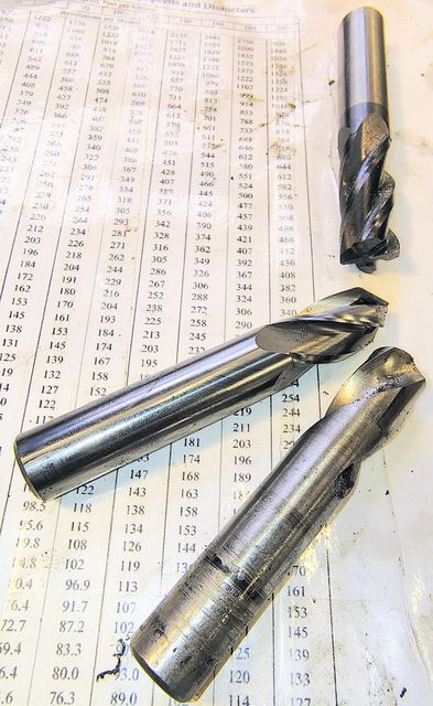
An end mill with a flat end and sharp corners. It cuts on its sides and its end, so it slots, pockets, profiles, and faces small areas, leaving a flat floor that meets the wall in a sharp line.
“Square end mill” and “flat end mill” are the same tool. A center-cutting end mill has edges that reach the middle of its end and can plunge straight down. A non-center-cutting one has a gap in the middle and has to ramp in or start in a drilled hole.
The end is a half sphere whose radius is half the tool diameter. It is the tool for 3D contoured surfaces and full-radius grooves. Passes leave small ridges called scallops; a smaller stepover leaves smaller scallops.
Right at the center of the tip the cutting speed is close to zero, so the very tip rubs more than it cuts. Tilting the tool, or cutting with the side of the ball, avoids that.
A flat end mill with a small radius ground on each corner instead of a sharp point. The radius makes the corner much stronger and leaves a matching fillet where the wall meets the floor.
Called out by two numbers, the diameter and the corner radius. Good for roughing, and for floors where the print allows a fillet. It will not leave a sharp inside corner; see Fillet / radius.
An end mill with a wavy or serrated cutting edge that breaks chips into small pieces. That lets it remove a lot of metal with less load, but it leaves a ridged wall that needs a finish pass.
Shop slang: corncob, rougher, hogger. Not the same as “roughing” the operation. You can rough with any end mill; see Rough.
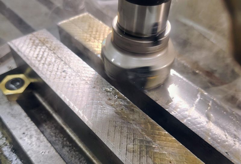
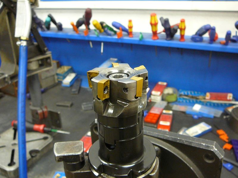
A large-diameter cutter body that carries several replaceable carbide inserts around its rim. It flattens the top of a part quickly with shallow, wide passes.
Typical first tool on a saw-cut plate. It is made for facing, not for plunging or cutting deep walls. See Face.
A cutter with a center bore and drive slots instead of a shank. It mounts on a shell mill arbor and is held on by a center screw. Many face mills are built as shell mills, so the two words overlap.
A tall shell mill with rows of inserts up its sides, for deep shoulders, is often called a porcupine cutter.
A single cutting tool, often a lathe-style tool bit or one insert, held at the end of an arm or body that swings in a wide circle. It takes light facing cuts and leaves a fine finish over a wide area for little money.
Common on manual mills and for one-off jobs. It is slow because one edge does all the work, and an unbalanced arm limits how fast it can spin.
A cutter with angled edges that bevels edges and breaks sharp corners as it follows a toolpath. A 90° tool leaves a 45° chamfer.
Watch the label: some tools are marked by the included angle (90°) and some by the angle per side (45°). Many shops run one around every edge of the part as the last tool. See Chamfer.
A ball-shaped cutting head, more than a half sphere, on a thin neck. The ball can reach under a ledge or cut the back side of a feature that a straight tool cannot see.
Use: deburring the back edge of a hole or wall, or cutting an undercut on a 3-axis machine. See Undercut.
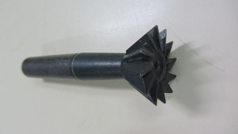
A cone-shaped cutter, widest at the bottom, that cuts the angled undercut walls of a dovetail. 45° and 60° are common angles.
Usually an end mill roughs the slot first, so the dovetail cutter only has to cut the angled walls. See Dovetail.
A disk of teeth on a narrow neck that cuts the wide bottom of a T-slot. An end mill cuts the narrow upright slot first so the neck has room.
Also used to cut grooves sideways into a wall. See T-slot.
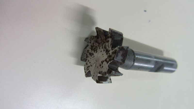
A thin disk cutter on a shank. It cuts a straight groove sideways into a wall, or plunges into a shaft to cut the half-moon seat for a Woodruff key.
Also used for side grooves such as a retaining-ring groove inside a bore. A Woodruff key is the half-moon shaped key; see Keyway.
A thin circular saw blade on an arbor in the spindle. It cuts narrow slots or parts pieces off.
Use: splitting a clamp collar, cutting a narrow slot. Thin blades want light feeds and very little runout.
An engraving tool is a small pointed cutter, often a carbide V tip, that cuts shallow text and lines. A drag engraver is different: a spring-loaded point that scratches the surface and does not spin. Deburring on a CNC usually means a chamfer mill or back-chamfer cutter running along the edges. By hand, it is a swivel blade dragged along the edge.
A burr is the thin ragged lip a cut leaves behind. Breaking edges is often a print note, not optional.
Other milling cutters
End mill anatomy, materials, and coatings
Flutes are the spiral grooves between the cutting edges, and the flute count is the number of edges. Fewer flutes leave more room for chips. More flutes give a stronger core and more edges sharing the work, which suits harder metals and finishing.
A common starting point: 2 or 3 flutes for aluminum, which makes big chips that need room, and 4 or more for steel and tougher alloys. The end views in the first photo above show 2 and 4 flutes.
The helix angle is how steeply the flutes twist around the tool. Common angles run from about 30° to 45°. A higher helix cuts more smoothly and lifts chips up and out.
A variable-helix or variable-pitch tool has flutes at slightly different angles or uneven spacing, so the edges do not hit at a steady rhythm. That breaks up chatter.
The words on a tool box or print: cutter diameter, length of cut (LOC, the fluted length), overall length (OAL), shank diameter, and on necked tools the reach, a relieved neck behind the flutes so the shank clears a deep wall.
Pick the shortest length of cut and stickout that reach the feature. Long tools bend and chatter; see Stickout.
High-speed steel (HSS) is tough and cheap but softens at a lower temperature, so it runs slower. Cobalt (HSS-Co, often M42) is HSS with cobalt added for more heat resistance. Solid carbide is tungsten carbide grains in a cobalt binder: much harder and stiffer, runs several times faster, but brittle, so it chips if it chatters or gets bumped.
CNC shops mostly run solid carbide end mills and carbide inserts. HSS and cobalt still show up in drills, taps, and manual work. A “cobalt” drill is HSS with cobalt in it, not carbide.
Thin, hard layers on the cutting edge. TiAlN and AlTiN (titanium aluminum nitride; the order of the letters hints at which metal there is more of) hold up to heat and are common for steel, stainless, and titanium.
For aluminum, tools are often uncoated and polished, or carry ZrN or a diamond-type coating, because aluminum tends to stick to aluminum-bearing coatings. Color is not a reliable ID. Read the label.
Hole-making tools
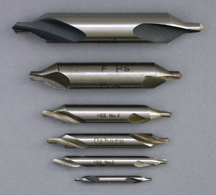
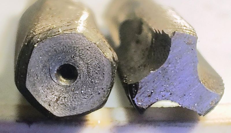
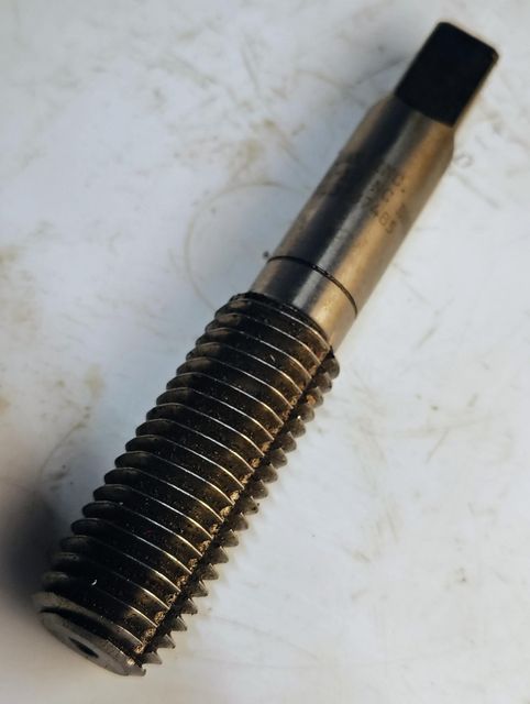
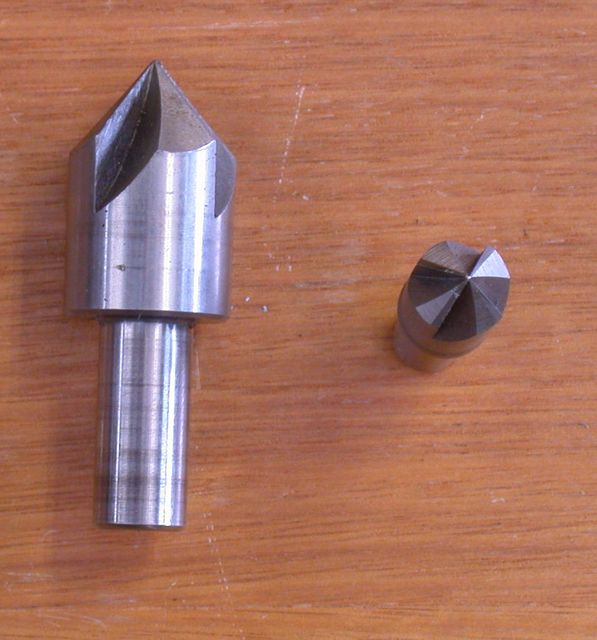
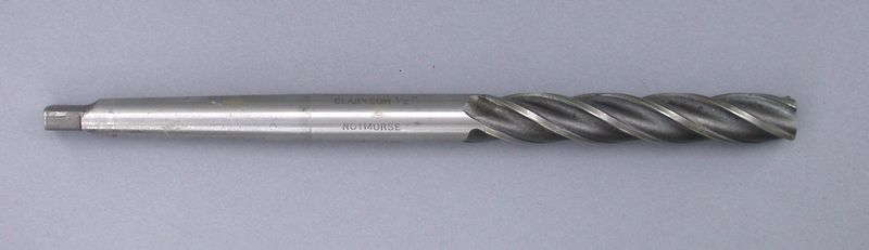
A spot drill is short and stiff, with a pointed tip (90°, 120°, and 140° are common), and makes a small cone so the real drill starts on location instead of wandering. A center drill is a combined tool, a small pilot tip plus a 60° cone, made to cut center holes for lathe centers.
A center drill can spot a hole, but its small pilot breaks easily and its 60° cone does not match a drill point. A common rule is a spot angle equal to or a little wider than the drill’s point, so the drill’s tip touches first and centers itself.
Twist drills come in length families. Jobber length is the everyday standard. Screw machine length is much shorter and stiffer, and “stub” usually means the same short length (catalogs differ). Taper length and extra-long drills reach deeper.
On a CNC, use the shortest drill that reaches; it starts straighter and bends less. Common point angles are 118° and 135°; a split point helps a drill start without walking.
The angle of the flutes to the drill axis. German standards group HSS twist drills into three application types (DIN 1836, used by the DIN 1414 drill spec): Type N (normal, roughly 25–35°) for general steels; Type H (low helix, roughly 10–20°) for hard, brittle, or short-chipping materials such as cast iron, brass, bronze, and some plastics; and Type W (high helix, roughly 35–45°) for soft, long-chipping materials such as aluminum and copper. Ranges vary by source.
Brass usually takes a low-helix Type H drill, not a high helix: it grabs and pulls a sharp, steep flute into the work. English catalogs often say "slow spiral" for H and "high helix" or "fast spiral" for W. For aluminum aerospace parts, high-helix drills with polished flutes clear chips better, and carbide parabolic-flute drills are common on CNC. Compare end mill helix angle.
A spiral point (gun) tap has straight flutes with an angled grind at the front that pushes chips ahead of the tap, out the bottom of the hole. It is meant for through holes. A spiral flute tap has twisted flutes that pull chips back up and out, for blind holes.
A spiral point tap in a blind hole packs chips into the bottom and can snap. See Thread / tap.
A tap with no cutting edges. It pushes the metal into thread shape instead of cutting it, so it makes no chips. It needs a material that flows, such as aluminum and many steels.
Slang: roll tap, cold-form tap. It needs a larger tap drill than a cut tap of the same thread, so use the tap maker’s form-tap drill size, not a cut-tap chart.
Names for how long the chamfered lead on the tap’s tip is. Taper: long lead, roughly 7 to 10 threads, the easiest to start. Plug: roughly 3 to 5. Bottoming: roughly 1 to 2, so it threads closest to the bottom of a blind hole.
Plug is the common default on a CNC. Bottoming taps are for blind holes that need full threads close to the bottom.
A multi-flute finishing tool that takes a small amount out of a drilled hole to reach an accurate size and a good finish. Machine (chucking) reamers have straight or spiral flutes. Hand reamers have a square drive end and a long tapered lead.
Drill a little under size and leave the reamer only the small amount its maker calls for. It follows the hole that is there; it will not fix location. See Ream.
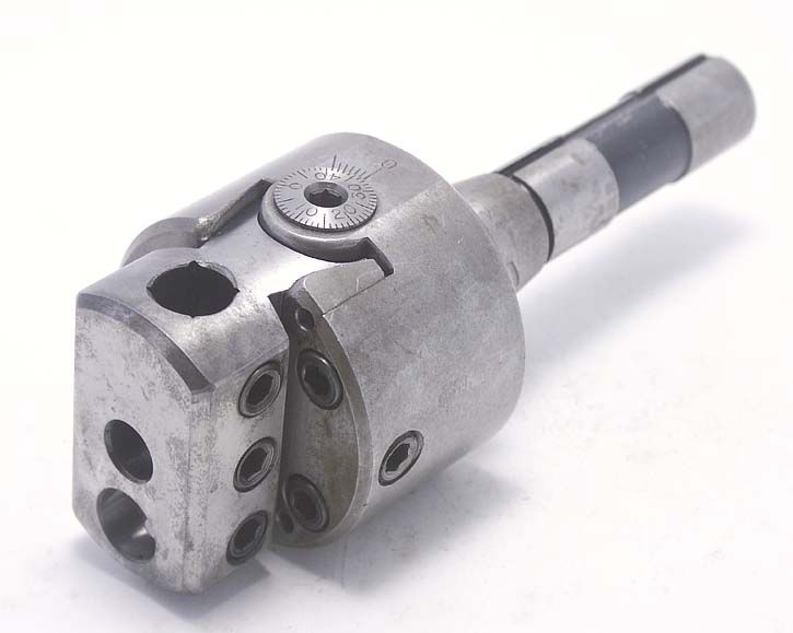
A boring bar is a single-point cutter on a bar that enlarges a hole that is already there. On a mill the bar sits in a boring head, which has a screw dial that slides the bar off center in small, known steps, so each pass makes the hole a known amount bigger.
Used for precise bores, such as bearing fits, when no reamer is the right size. Check whether the dial reads in diameter or in radius before you turn it. See Bore.
A counterbore tool has a flat cutting end, often with a pilot that rides in the existing hole, and cuts the flat-bottomed step a socket-head cap screw sits in. A countersink tool is a cone that cuts the angled seat for a flat-head screw: 82° is common for inch screws, 90° for metric, and 100° for many aerospace flush fasteners.
On a CNC, counterbores are often just milled with an end mill on a helical path, and countersinks cut with a chamfer mill or spot drill of the right angle. See Counterbore and Countersink.
Indexable inserts
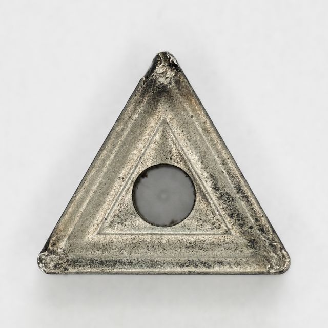
A small replaceable cutting tip, usually carbide, screwed or clamped into a tool body such as a face mill, boring bar, drill, or lathe tool. When an edge wears, you index (turn) it to a fresh edge, then replace it.
The body outlives many inserts. An insert that is not fully seated, or one with a different shape or grade in the same cutter, gives an uneven cut.
Inserts carry an ISO code such as CNMG 120408. The letters give the shape (C = 80° diamond, D = 55° diamond, R = round, S = square, T = triangle, V = 35° diamond, W = trigon), the clearance angle (N = 0°, a “negative” insert), the tolerance class, and the hole and chipbreaker type. The numbers give edge length, thickness, and corner radius (08 = 0.8 mm).
Inch catalogs show the same insert as CNMG 432. A clearance letter other than N means clearance is ground in, a “positive” insert.
The grade is the maker’s recipe of carbide and coating. ISO groups grades by the material they cut, with a letter and a color: P blue (steel), M yellow (stainless), K red (cast iron), N green (aluminum and other nonferrous), S orange (heat-resistant alloys and titanium), H gray (hardened steel).
Right shape, wrong grade means short life or chipped edges. Grade names are brand-specific; the ISO letter is the common language.
Tool holding
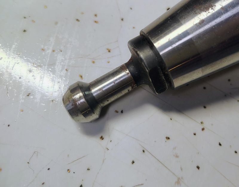
The tapered socket in the spindle and the matching cone on every holder. CAT40 and BT40 both use the steep 7:24 taper in size 40, but CAT has inch threads and its own flange, and BT has metric threads, so holders and pull studs do not swap between them. HSK is a short, hollow taper that clamps on both the taper and the flange face, which is stiffer and more accurate at high RPM.
Bigger machines use size 50 for heavier cuts. Find out what taper the machine has before buying any holder.
The part that joins the cutter to the spindle: a taper on one end, a way of gripping the tool on the other (collet, set screw, shrink fit, hydraulic), and a flange the tool changer grabs.
Holder plus cutter is one tool assembly. It gets one tool number and one length offset.
A threaded knob screwed into the back of the holder’s taper. The spindle’s drawbar grabs it and pulls the holder up tight into the taper.
Machine builders use different pull-stud shapes even on the same CAT40 or BT40 taper. Use the one the machine maker specifies, tightened as specified; a wrong or loose stud can let a holder drop out.
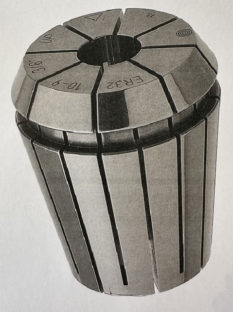
An ER collet is a slotted spring sleeve that squeezes a round shank when its nut is tightened. ER is the most common collet system on CNC mills. Each collet closes over a small range, about 1 mm on the common sizes, and the size number (ER16, ER20, ER32, ER40) says how big a shank the system takes.
The collet chuck is the holder body and nut. One holder takes many shank sizes by swapping collets. Snap the collet into the nut before threading it on.
A plain bore with one or two set screws that bear on a flat ground into the tool shank, called a Weldon flat. The tool cannot pull out, but the screw pushes it to one side, so runout is higher than with a collet or shrink fit.
A holder whose bore is slightly smaller than the tool shank. A heater expands the bore, the tool drops in, and as it cools the holder grips the shank all the way around. Low runout, strong grip, and a slim nose for reaching into deep pockets.
Needs a shrink machine, and the tool shank has to be made to a close tolerance.
Turning one screw pressurizes oil behind a thin sleeve, which squeezes the shank evenly. Low runout, good damping, and quick tool changes with a hex key.
A favorite for finishing, reaming, and drilling. Check the maker’s limits before heavy side-load roughing.
A heavy holder with a thick nose and a large locking ring that collapses a sleeve around a straight shank, often with a reducing collet inside. Built to grip hard for heavy roughing.
A holder with a short pilot, two drive keys, and a center screw that carries a shell mill or face mill.
A three-jaw chuck, tightened with a key or by hand (keyless), that grips round shanks over a wide range. Common on manual mills and drill presses.
Less common on a CNC, where collets grip more accurately. A drill chuck is not made for side milling loads.
Rigid tapping: the control locks spindle rotation and Z feed together exactly, so the tap can sit in a solid holder. A tension-compression tap holder floats a little up and down to absorb mismatch on machines without rigid tapping. A self-reversing tapping head reverses the tap mechanically.
How far the tool hangs out of the holder. Keep it as short as the job allows; a long stickout bends more and chatters.
Bending grows with roughly the cube of the length, so twice the stickout bends about eight times as much, all else equal. See Tool deflection.
A reference diameter on the holder’s taper that the machine and the presetter measure tool length from. It is a fixed point on the taper, not a mark you can see.
Tool length is gauge line to tip. Some setups measure from the spindle face instead, so know which one your shop uses.
A stored number that tells the control how far each tool’s tip is from the reference point, so the program’s Z zero lands on the part for every tool. On Fanuc-style controls it is an H number turned on with G43.
A wrong H number, or a missing G43, is a classic crash. Matching H to the tool number is a convention, not something the control enforces.
A tool setter sits on the machine table, as a touch switch or a laser, and measures each tool’s length (and sometimes diameter) inside the machine. A presetter is a separate instrument off the machine that measures assembled holders before they go in, so the machine keeps cutting while tools are set.
Either way, the number ends up in the tool offset table.
The automatic tool changer swaps holders between the spindle and the tool magazine, which may be a carousel, an umbrella, a chain, or a side-mount with a swing arm. Each storage spot is a pocket. Programs call tools by T number, and the machine tracks which pocket holds which tool.
On many swing-arm changers tools move between pockets, so pocket number and tool number can differ. Large-diameter tools may need the pockets next to them left empty.
Workholding and setup
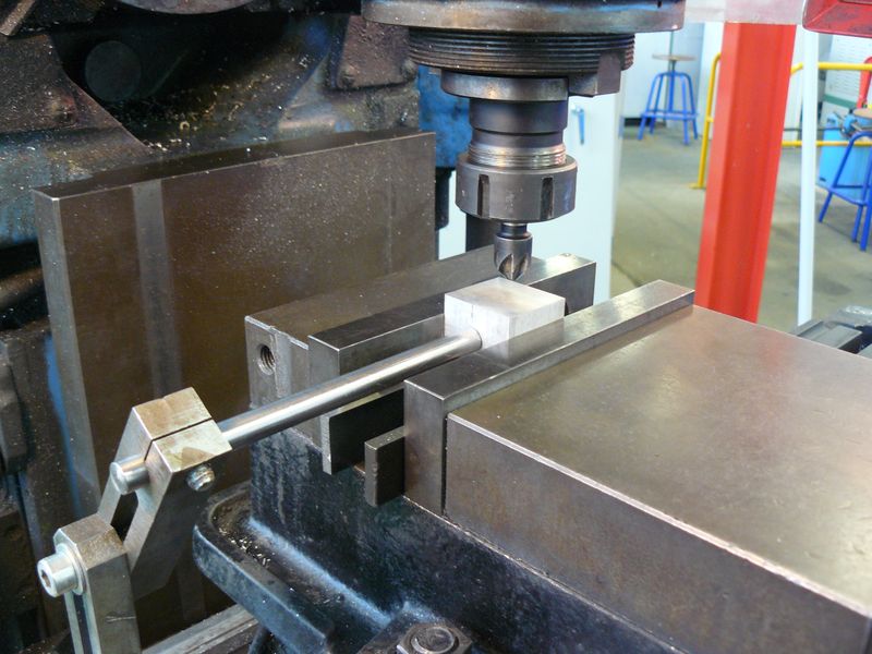
The default CNC workholding: a fixed jaw and a moving jaw on a screw, bolted square to the table. “Kurt-style” means the common design where the moving jaw is pulled down as it clamps, so the part does not lift.
Indicate the fixed jaw straight with the machine axis before using it. The fixed jaw is the reference; the moving jaw just pushes. See Fixture / jig.
Hard jaws are the hardened steel jaw plates that come with the vise, smooth or serrated. Soft jaws are aluminum or mild steel plates you machine to fit the part, so odd shapes or finished parts sit in a pocket that matches them.
Typical use is op 2: the part is flipped and dropped into a pocket cut in soft jaws, so it lands in the same place every time and does not get marked.
Ground steel bars, in matched pairs, set under the part in the vise to raise it to a known height and keep it level.
Tap the part down with a soft mallet after clamping. If a parallel still slides, the part is not seated.
A stop clamped to the vise that each part is pushed against, so every new part lands in the same place along the jaws without re-indicating.
This is what keeps one work offset good part after part in production.
A flat plate bolted to the table with a grid of tapped holes and precise locating holes. Vises, clamps, and fixtures bolt to it in repeatable spots.
A strap (toe) clamp is a slotted bar pressed onto the part by a stud and nut threaded into a T-nut in the table slot. A step block, a stepped and serrated riser, holds up the back end of the strap at the right height.
Put the stud closer to the part than to the step block, and keep the strap level or tipped slightly toward the part, so most of the force goes into the part.
Small clamps that push on the side of the part, often with an eccentric or cam screw that moves a jaw sideways and slightly down. They stay below the top of the part, so the cutter can reach the whole top.
Use: holding plates on a fixture plate so the outside profile can be cut all the way around.
Quick-change workholding: receivers in the table lock onto studs on the bottom of a vise or fixture, locating it repeatably and clamping it in seconds.
Swap a whole setup without re-indicating, and the work offsets stay good.
A narrow, tall vise that grips a small dovetail machined on the bottom of the stock. Holding only a few millimeters lets a 5-axis tool reach almost all of the part from many angles.
Op 1 cuts the dovetail, op 2 machines the part, and the dovetail is cut off at the end. See Axes.
A rotary table (4th axis) bolts to the machine table and turns the part about one axis. A trunnion is a cradle that tilts, usually with a rotary platter on top, giving the two rotary axes of a table-type 5-axis machine.
See 4-axis and 5-axis, and the Tombstone, which stands on a rotary indexer.
Thin plates that would bend under clamps can be held flat by vacuum through a grid table, or, for light cuts, with double-sided tape or superglue. Holding force is low, so cuts have to be light.
Check the shop’s approved method before using tape or glue on a production part.
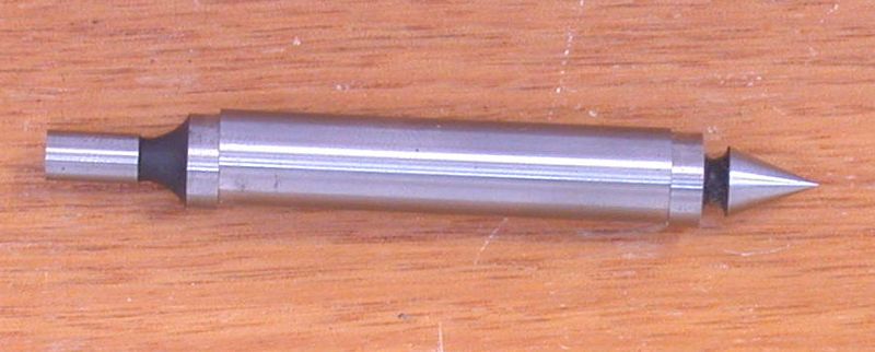
A two-piece probe spun in the spindle. As its tip touches the edge of the part it stops wobbling and then kicks sideways; at that moment the spindle center is half the tip diameter from the edge.
A common tip is 0.200 in across, so the edge is 0.100 in from the spindle center. Electronic edge finders light up on contact instead. A spindle probe does this job on most modern CNCs.
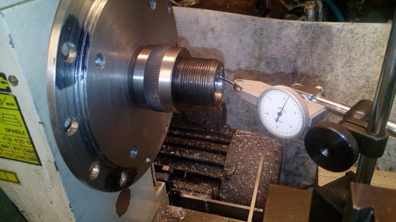
A lever-type indicator: a small stylus swings and a dial shows the movement in thousandths or finer. Used to straighten vises, sweep bores, tram the head, and check runout. A plunger dial indicator is different; its stem moves straight in and out.
Keep the stylus close to parallel with the surface. At a steep angle the reading is off (cosine error). See Runout.
A touch probe that goes in the spindle like a tool. The control moves it until the stylus triggers, records the position, and can set work offsets, find bore centers, or check features automatically.
Treat it like glass. Running a probe into the part at a rapid move is an expensive crash.
Speeds, feeds, and machine terms
Surface feet per minute: how fast the cutting edge moves across the material. The recommended number comes from the tool maker for a given tool and material, and it does not depend on tool size. Metric shops use meters per minute (Vc).
Revolutions per minute, worked out from SFM and tool diameter: RPM = SFM × 3.82 ÷ diameter in inches (3.82 is 12 ÷ π). A small tool needs a much higher RPM than a big one for the same SFM.
The math only: 400 SFM on a 0.5 in tool is 400 × 3.82 ÷ 0.5, about 3,056 RPM. It is the S number in the program.
How thick a bite each cutting edge takes, in inches or millimeters per tooth. Too small and the tool rubs and heats up; too big and it chips or breaks. Tool makers publish chipload ranges by material and diameter.
Also written IPT or fz.
Table feed in inches per minute: IPM = RPM × number of flutes × chipload. It is the F number in a milling program.
The math only: 3,056 RPM × 3 flutes × 0.002 in per tooth is about 18.3 IPM. Drilling and tapping sometimes use feed per revolution (IPR) instead.
Toolpath styles that hold the tool’s engagement steady: a small width of cut with a deep depth of cut, using most of the flute length, at a high feed. “Adaptive” and “dynamic” are CAM names for it; trochoidal means moving in looping arcs, often to cut a slot.
A thin side cut makes a thinner chip than the chipload number (chip thinning), which is why these paths feed faster than a full-width slot. Wear spreads along the whole flute instead of the tip. See Stepover (WOC) and Stepdown (DOC).
In climb milling each tooth enters the metal thick and leaves thin. In conventional milling it enters thin and leaves thick. On a rigid CNC, climb is the usual default for better finish and tool life.
Conventional can be the safer choice on a manual mill with backlash in the screws, because climb can pull the table into the cut.
Flood pours a stream of water-based coolant on the cut. Mist is a fine spray of coolant or oil in air. Air blast is just air to clear chips. Through-spindle coolant (TSC) pumps coolant at high pressure through the spindle and holder and out of holes in the tool, right at the edge, which helps most in deep holes.
In milling, clearing chips is often coolant’s biggest job; cutting the same chips twice ruins tools. M08 and M09 commonly turn flood on and off, but check your machine’s manual.
A vibration between tool and part that makes a loud squeal or buzz and leaves a regular wavy pattern on the surface. The setup is not stiff enough for the cut: long stickout, thin walls, weak workholding, or a speed the system does not like.
Fixes: shorter stickout, lighter width or depth of cut, a different RPM (sometimes faster, not slower), a variable-helix tool, better clamping.
Work metal welding onto the cutting edge. It changes the edge’s shape, tears the surface, and can pull chunks off the tool when it breaks away. Common in gummy materials such as aluminum and some stainless.
Fixes: the right surface speed, a sharp polished tool, the right coating or none, and good coolant or lubrication.
The cutter bending away from the cut under load. Walls come out tapered or the wrong size, and the finish suffers.
Long, thin tools bend the most. A spring pass, a repeat pass at the same size, cleans up what bending left behind.
The work coordinate system (WCS) is the X0 Y0 Z0 the program measures from, usually a datum corner or center on the part. The control stores where that point sits in machine coordinates as a work offset, G54 through G59 (plus extra offsets on many controls).
The program says G54; you set G54 with an edge finder or probe at setup. Two vises on the table can be G54 and G55. See Datum.
Knobs or buttons on the control that scale the programmed feed and spindle speed by a percentage while the program runs. They are used to run a new program slowly the first time and to tune a cut.
Rapid override is usually a separate control. If a cut always needs the knob turned, fix the program.
Wobble while something spins. A different problem from a wrong diameter.
How much a surface moves in and out as it rotates about an axis. You see it with an indicator on the spinning part, or on a tool in the spindle. Total indicator reading is the full needle swing.
A shaft can measure the right diameter at every station and still run out if the centerline is bent or the diameter was cut off-axis. Runout is wobble, not “the size is wrong.”
The cutter or holder orbits instead of spinning on its own center. Holes come out large, walls taper, and tools wear fast even when the program numbers are right. Check it in the spindle before you chase the part.
The part’s own surface is not centered or not straight about the axis you are spinning it on. That can be how it was machined, how it was chucked, or how the stock was. Fixing the program’s diameter will not straighten a wobble.
How to read a US aerospace print. This follows ASME Y14.100 (drawing practices) and ASME Y14.5 (dimensioning and tolerancing), with inch units and third-angle projection. The sheet below is an original teaching example, not a real part. All tolerance values on it are examples. The tolerance block and notes on your actual drawing always govern.
How to read a print, step by step
Title block and change control
The box in the lower right. It holds the drawing (part) number, title, sheet size, scale, sheet x of y, the drawn/checked/approved signatures, the CAGE code, the current revision, and usually the tolerance block and projection symbol.
The suffix after the part number, such as EX12345-1. It lets one drawing define several related parts (lengths, hole options, finishes), with the differences shown in a table or in notes.
Some companies use odd and even dash numbers for left-hand and right-hand (mirror) parts. Read the drawing’s own notes rather than assuming.
Commercial and Government Entity code: a five-character ID for the design activity (the company or site that owns the design). The CAGE code plus the drawing number identify a drawing uniquely, because two companies can use the same number.
Each released change bumps the revision, usually A, B, C… (letters that look like numbers, such as I, O, Q, S, X and Z, are not used). The revision block, usually in the upper right, records each revision with its zone, a description, the date and the approval.
Always check the revision on the print against your traveler. Making a part to the wrong revision is a common, expensive mistake.
Engineering change notice or order: the formal document that authorizes a change to a released drawing. The change shows up as a new revision. Some changes are issued as an advance notice before the drawing itself is updated, and these count too.
Notes and tolerances
The “unless otherwise specified” box. It sets the default tolerance for any dimension without its own, usually by number of decimal places. A typical example is .XX ±.01, .XXX ±.005, angles ±0.5°; real values vary by company and drawing.
So .50 and .500 do not mean the same thing: the extra decimal place tightens the tolerance.
The numbered notes that apply to the whole drawing: governing standard, material, finish, process specs, edge breaks, marking, and so on. Read them before you look at any single feature, because they change what the features mean.
“Dimensions apply after finish” means the coating counts, so plated or anodized features have to be machined to allow for it.
A numbered note whose number appears inside a triangle (flag) on the drawing. It applies only to the features or areas where that flag is placed, not to the whole part.
A general note that asks for a small chamfer or radius on every sharp edge, often with a range such as .005–.015. It removes burrs and cut hazards without becoming a real chamfer.
Notes that point to other documents: material specs (for example SAE AMS or ASTM), process specs (heat treat, anodize, primer, penetrant inspection) and military specs. The spec, at the revision called out, is part of the requirement.
Boeing drawings also call out internal specs: BAC process specs and BMS material specs. Their content is company-controlled, so get them through your official channels instead of guessing what they say.
Never measure the paper to get a size. If a dimension you need is missing, ask engineering; do not scale it off the print or the screen.
Views and lines
US drawings use third angle: each view is placed on the side it is seen from. The top view goes above the front view and the right view to its right. First angle, common in Europe and Asia, swaps them. The symbol is a truncated cone shown as concentric circles plus a side view; in third angle the narrow end of the cone points toward the circles.
A thin long-dash, short-dash line marking an axis or a hole center, or a crossed center mark on a circle. It is a line, not a dimension.
A thin long-dash, double-short-dash line showing an alternate position, a neighbouring part for reference, or repeated detail. Whatever it outlines is not part of what you are making.
A view of the part as if it were sawn along the cutting plane line. That line is thick, dashed, and has arrows that point the way you are looking. Cut material is crosshatched. Both the plane and its view carry the same letters, such as SECTION A-A.
A small area circled and lettered on the main view, then redrawn larger elsewhere on the sheet as, for example, DETAIL B SCALE 4:1. The dimensions are still full size; only the picture is enlarged.
A view projected square to an angled surface, so that surface and its holes show at true size and shape instead of foreshortened.
The grid formed by numbers along the top and bottom borders and letters along the sides. A location such as “C6” points to one rectangle of the sheet, which makes it quick to find a feature, a section, or a revision change on a big drawing.
Dimensions and callouts
A dimension in a box. It is a theoretically exact value with no tolerance of its own; the tolerance comes from a feature control frame, usually position or profile. The tolerance block does not apply to it.
A dimension in parentheses, such as (2.25). It is for information only, usually repeating a value that follows from other dimensions, and it is not inspected.
The tolerance is stated as the high and low limits instead of a nominal value and a tolerance, with the high limit on top, for example .3765 over .3750. There is nothing to add or subtract: any size between the two is good.
Bilateral means the size can vary both ways: 1.50 ±.01, or unequally, such as +.01/−.02. Unilateral means it can vary in one direction only, such as 1.500 +.000/−.005, which is common where a part must never be oversize.
A datum feature symbol is a boxed letter on a leader that ends in a filled triangle on the surface or feature that becomes the datum. A datum target is a circle split in two, such as A1: it specifies only certain points, lines or small areas of a surface to contact, which suits castings, forgings and thin parts that are not flat enough to rest on whole. See Datum.
“4X” means the callout applies to four identical features. “TYP” (typical) is older usage meaning “and all the ones like it”. Y14.5 does not define TYP and prefers an explicit nX, because TYP leaves you guessing how many features it covers.
Callouts are read in order: count (4X), diameter ⌀ and depth (or THRU), then any counterbore ⌴, countersink ⌵ (with included angle, such as 100° for many aerospace flush fasteners) or spotface, each with its own diameter and depth ↧. See Counterbore and Countersink.
For example 1/4-28 UNF-3B: .250 nominal size, 28 threads per inch, Unified Fine series, class 3 (tighter fit), B = internal. External threads use A, as in 2A or 3A. Depth or THRU follows. See Tap.
Fasteners, inserts and other hardware shown with MS, NAS, AN or similar standard part numbers are bought to that standard, not made from your drawing.
The check-mark symbol (ASME Y14.36) sets surface roughness, usually as Ra in microinches on US drawings. As a rough guide, 125 is a normal milled finish, 63 is a good finish cut, and 32 or lower usually needs finishing passes or grinding. A bar across the symbol means material removal is required.
Standards and models
Y14.100 covers engineering drawing practice in general: title blocks, notes, and how drawings are organized. Y14.5 covers dimensions and GD&T. Related standards: Y14.2 (line types), Y14.3 (views), Y14.35 (revisions), Y14.36 (surface texture) and Y14.41 (digital product definition, or MBD). A drawing names the edition it follows, such as Y14.5-2018.
The 3D CAD model, with tolerances and notes attached (PMI), is the authority, and any drawing is reduced or left out. Much of the newer aerospace work is defined this way. The GD&T rules are the same; you just read them in the model.
If a note says the model governs, a print of the drawing alone is not the full requirement.
Geometric dimensioning and tolerancing, in shop language. Symbols here are the common ones so you can recognize a frame. This page does not quote the standard.
A drawing language for form, tilt, location, and shape, usually tied to datums. A plain ± size still matters, but GD&T says what kind of error is allowed: a face may be the right height and still be warped, tilted, or in the wrong place.
The rectangular box on the drawing. Read left to right: geometric symbol, the tolerance (a diameter sign means a round zone; a material modifier may sit with it), then the datum letters that tolerance is measured from.
That frame is position, a 0.010 diameter zone, at maximum material condition, relative to datums A, B, and C. The sentence is under Position below.
Every point on a surface must lie between two parallel planes the stated distance apart. No datum. A face can be flat and still be tilted relative to the rest of the part; tilt is an orientation control.
A line on a surface, or sometimes an axis, must stay inside a straight zone. Applied to a surface, it does not need a datum. It does not by itself make the whole surface flat.
Each cross-section circle of a round surface must sit between two concentric circles. It checks roundness one slice at a time. It does not control taper, and it does not locate the axis.
The whole cylindrical surface must lie between two coaxial cylinders. That folds roundness, straightness along the length, and taper into one control. No datum.
A surface or an axis must be 90° to a datum, inside the tolerance. The basic angle is square; you do not also write 90° next to it.
Example: a hole axis square to face A.
A surface or axis must not tilt relative to a datum. The two can still be the wrong distance apart; distance is location or a size, not parallelism.
Same idea as perpendicularity, but the basic angle on the drawing is not 90°. The frame limits how far the surface or axis may wander from that angle. It does not set the angle by itself; the drawing does.
The everyday location control. The axis or center of the feature must lie inside a tolerance zone, usually a cylinder whose diameter is the number in the frame, placed at true position from the datums.
Position ⌀ 0.010 Ⓜ to A, B, and C means the hole’s axis has to stay inside a 0.010-diameter cylinder at the true location from those datums, and that cylinder is allowed to grow if the hole is larger than its maximum-material size.
An old control on how well the midpoints of a round surface are centered on a datum axis. It is hard to inspect, and it is not the same word as “concentric” in casual shop talk. ASME Y14.5-2018 dropped the concentricity symbol. Position or runout covers the cases people actually mean.
The old partner of concentricity, for a midplane instead of an axis. The symbol was dropped in ASME Y14.5-2018 as well. Use position.
Spin the part about a datum axis and watch one cross-section. The indicator must stay inside the tolerance at that slice. It limits how round that circle is and how centered it is. Move the indicator along the part and each new slice is its own check.
The indicator must stay inside the tolerance everywhere on the surface while the part spins, not just on one circle. On a diameter that also limits taper. On a face it limits wobble of the whole face.
One 2D slice through a contour must stay inside a uniform band wrapped around the true shape. It is the outline, not the whole surface.
The whole 3D surface must stay inside a zone wrapped around the true surface. This is the general control for a contoured face when position or flatness is the wrong shape of tolerance.
Maximum material condition: the size at which the feature has the most material the size tolerance allows. That is the smallest hole, or the largest pin. In the frame it is a letter M in a circle next to the tolerance.
When position is specified at MMC, the position zone grows by however much the feature departs from that MMC size. A hole that is larger than its smallest allowed size gets extra location slack, because a mating pin still clears.
Example: position ⌀ 0.010 at MMC on a hole whose smallest size is 0.250. If that hole measures 0.254, the position zone is 0.010 plus 0.004, so ⌀ 0.014, provided the rest of the callout allows it.
Regardless of feature size: the geometric tolerance stays the number in the frame no matter where the size lands inside its limits. There is no bonus. In current ASME Y14.5 this is the default when the frame shows no material modifier. You do not add a symbol to get it.
The US standard people mean by “current GD&T.” One practical change: it dropped the concentricity and symmetry symbols. This page only describes the ideas. Read the real callout on the drawing, and the standard if you need the legal definition. Nothing here is a company-specific spec.
Plain names for the classic Boeing 707, the early four-engine swept jet, so a fitting on the airplane is not confused with a fixture on the bench. Wording here is original. It is not a structural repair manual, and the sketches are not Boeing figures.
Variant note, only where it was checked: early 707-120 and -320 airplanes have a Krueger leading-edge flap between the inboard and outboard engines. The 707-320C, and later 707-320B Advanced airplanes with that wing, use a three-section leading-edge flap arrangement, and those later wings dropped the small underfin. Anything past that is left generic on purpose.
Boeing photos
Free Wikimedia Commons photographs, saved on this site. The 737 is the closest free Boeing photo match for the leading-edge layout named above: slats outboard, a Krueger flap inboard. These frames show a 707 side view, 707 engines and gear, a 737 tail, and 737 trailing-edge flaps. They are not a close-up of a Krueger flap. Boeing maintenance manuals are not reproduced, and no handbook figure is copied here.




Wing and flight surfaces
The left and right wings are the lifting surfaces outboard of the body. Each is a swept cantilever that also carries fuel, the aileron, the flaps, and two podded engines, and it dumps that bending into the center section.
The closed beam inside the wing: spars, ribs, and skin working together. Bending is carried mainly by the spar caps and the skin, and twist is carried because the skin closes the box.
A spanwise beam. Published descriptions of the classic 707 call the wing a two-spar aluminum structure, front and rear. The spars take bending and give the ribs and skin a frame to close against.
A chordwise former that holds the airfoil shape and keeps the spars spaced. Air load on the skin is passed through the ribs into the spars.
The aluminum sheet on the outside of the wing. It is not a wrapper laid over the structure: with the spars it closes the box, so a crack in it is a strength problem.
A small spanwise stiffener fastened to the inside of the skin. It keeps the skin from buckling between ribs when the wing bends.
The forward nose of the airfoil, ahead of the front spar. On the 707 it is also where the leading-edge flap lives, so it is a hinge line as well as a shape.
The aft, thinning end of the wing behind the rear spar. Flaps and the aileron hang here.
The hinged surface on the outboard trailing edge. One goes up while the other goes down, and that rolls the airplane. The hinge fittings see a reversing load every time the wheel moves.
A trailing-edge surface that adds lift and drag for takeoff and landing. The 707’s main flaps are described as Fowler flaps: they move aft as they deflect, instead of only hinging down the way a plain flap does.
A panel on top of the wing that rises to kill lift and add drag. On the ground it puts the weight on the wheels. In the air it can help a roll or a descent. The hinges sit in the wing just ahead of the panel.
The smooth cover that blends the wing root into the fuselage. It guides air. It is not the joint that holds the wings on. That job belongs to the carry-through.
A panel hinged from the underside of the leading edge that folds out and forward, making a blunter nose for low speed. It is not a slat. Early 707-120 and -320 airplanes have this flap between the inboard and outboard engines. The 707-320C, and the 707-320B Advanced airplanes that use that later wing, have a three-section leading-edge flap layout. How far the panels run along the span depends on the variant.
A slat is a leading-edge piece that moves forward and opens a slot over the fixed nose. Later jets use them heavily. The 707’s leading-edge device is a Krueger flap, not that kind of slat.
Empennage
The fixed tail surface that keeps the nose from wandering in pitch. The elevators hinge from its trailing edge, so its rear spar is also the elevator’s hinge support.
The hinged surface on the horizontal stabilizer that raises or lowers the nose. Its load goes through hinge fittings into the stabilizer.
The fixed upright fin that keeps the nose from wandering left and right. The rudder hinges to it. Early 707s also had a small ventral fin under the tail. That underfin came off on the 707-320C and on 707-320B Advanced airplanes when the later leading-edge flaps changed the wing.
The hinged surface on the fin that yaws the nose left or right. Like the elevator, it is a moving panel on fittings, not part of the fin’s fixed spar.
Fuselage
The long body: pressure vessel, people or cargo, and the beam that ties the wing to the tail. It is a skin-and-stringer shell on frames, not a solid tube.
A hoop in cross-section. Ordinary frames keep the shell round. A bulkhead is a heavier frame that closes a bay or picks up a big load.
A heavy member running lengthwise along the fuselage, bigger than a skin stringer. Longerons carry body bending from frame to frame.
The outer aluminum shell of the body. In the cabin it is also the pressure-vessel wall, so a window cutout or a lap joint is structure, not trim.
The lengthwise band of skin and frames that holds the row of cabin windows. The repeated holes make this strip a fatigue spot, which is why the joints and clips around the windows get attention.
The forward tip of the body, ahead of the flight deck, including the radome area. It sits forward of the front pressure bulkhead, so it is not the same shell as the cabin.
The crew compartment just behind the nose, inside the pressure shell. Its window frames break the skin the same way a cabin window does, only larger.
The pressurized compartment between the pressure bulkheads, whether it is fitted for seats or freight. Floor beams pick up local loads. The shell around them holds the pressure.
The taper behind the rear pressure bulkhead. People do not sit there, but the fin and the stabilizer attach in this neighborhood, so it is still structure.
The wall, often domed, that closes the pressurized cabin at the front and again at the rear. Cabin pressure tries to blow it outward. It is primary structure, not an interior panel.
Landing gear and engine attach
The piece of wing box that runs through the fuselage and joins the left wing to the right. Bending from both sides meets here, which is why the heaviest “wing” structure is the part you cannot see.
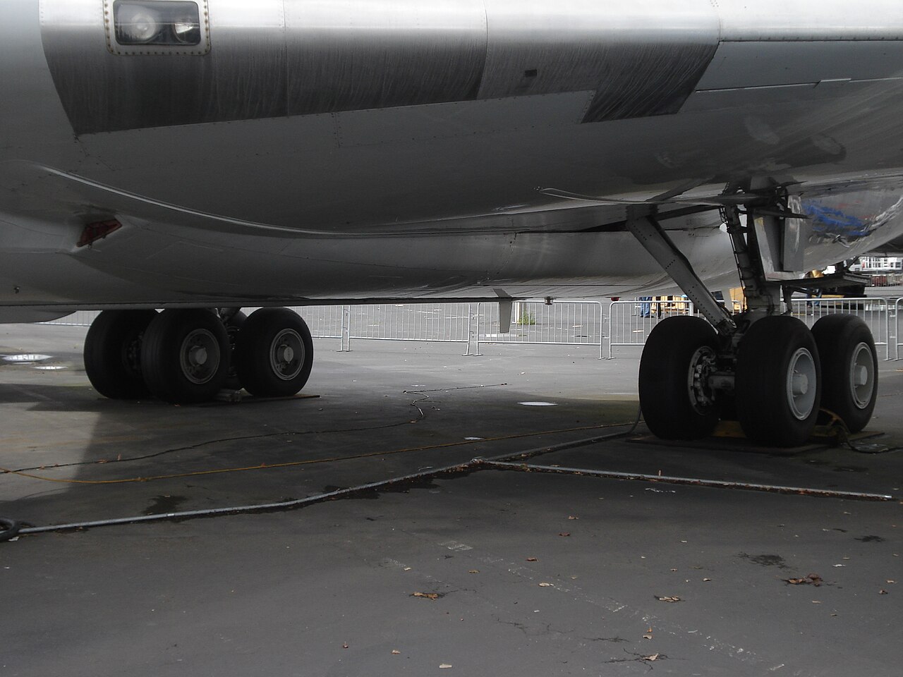
The nose gear under the forward fuselage and the main gears under the inboard wing, all retractable. They carry the airplane on the ground and the impact of landing. In the air they are a well and a set of doors.
The beams and lugs that lead landing-gear loads into the wing or the body. On the 707 the main gears attach at the wing, so those fittings put a concentrated load into the wing box instead of spreading it the way air load does. This is a high-level name, not a Boeing part number.
The structural strut that hangs each podded engine below and ahead of the wing. Weight, thrust, and torque go through a few attach fittings into the wing box. The 707’s engines are pods, not buried in the wing root.
The housing around the engine itself: inlet, cowlings, and the exhaust area. A lot of it is removable skin and doors. The pylon is the beam. The cowling is not.
Fittings people mix up, and shop fixtures
A lug or bracket that pins a moving surface, such as an aileron, flap, elevator, rudder, or spoiler, to the fixed structure and lets it rotate. It stays on the airplane. It is not a tool.
The heavy upper or lower flange of a spar. When the wing bends upward the upper cap is in compression and the lower cap is in tension, which is why a cap is a thick extrusion or a built-up member, not a piece of skin.
The flange along the edge of a rib, running from leading edge toward trailing edge, where skin or stringers fasten. “Chord” here is that direction. It is not the overall chord length of the wing, and it is not a music term.
A cover whose job is smooth airflow: wing-to-body, a flap-track cover, a gear door in that sense. Take it off and, if the airplane is still held together, it was a fairing.
A curved blend where two surfaces meet, such as the wing root flowing into the fuselage, used to soften the air in the corner. In the shop, fillet also means a machined radius. Here it means the aerodynamic blend, often built as fairing, not the bolted joint.
An airframe fitting is a lug, bracket, or attach part that flies: a hinge fitting, a pylon fitting, a gear fitting. A shop fixture is a tool that holds, drills, checks, or trims a part and never leaves the building. Same syllable, opposite jobs.
A shop tool that clamps a part in a known position so it can be machined, drilled, or assembled. It locates the work. It does not fly.
A shop tool that holds the part and also guides the drill, usually with a bushing, so the hole lands in the right place. The bushing is what makes it a jig instead of a plain clamp.
A shop tool for inspection. The part sits on locators, and gauges or indicators show whether the shape matches. It is not a setup you cut in.
A shop tool that holds a skin, extrusion, or panel so the edge can be routed or trimmed to a line. It sets the outline. It is not the airplane’s trailing edge.
A shop frame that holds two or more pieces in the right relationship while they are fastened. This is the “jig” people mean when they say a panel was built in a jig.
A shop tool with a shaped nest that supports a formed skin or extrusion so it does not spring while you drill or trim it. The nest matches the curve. It is tooling, not a rib.
Public pages behind the airframe names, plus free places to keep learning machining. The 737 is the closest free Boeing photo match: slats outboard, a Krueger flap inboard. Boeing maintenance manuals are not reproduced.
Free CNC machining training: video lessons on setups, tooling, CAM, and running mills and lathes. A free account is needed for the courses.
Free MIT course materials. For machining theory, 2.008 Design and Manufacturing II has metal-cutting lectures covering cutting forces, power, and chatter.
Where the tooling photos on this page came from. Each photo is credited with its author, license, and file page under the picture.
Labeled fuselage, wing, tail, landing gear, and flight controls in the Pilot’s Handbook of Aeronautical Knowledge.
Index of FAA handbooks, including the Aviation Maintenance Technician Airframe handbook FAA-H-8083-31B, which covers spars, ribs, skin, flaps, slats, and spoilers.
Open textbook chapter on the wing box: spar, rib, stringer, and skin.
Course reading on how ribs, spars, and skin share the wing’s loads.
Real 737 photographs of Krueger flaps, slats, and trailing-edge flaps. Linked only. Those pictures are not copied onto this page.
Overview of the classic four-engine jet. Photos live in the Boeing 707 category on Wikimedia Commons.
Closest free Boeing photo match for slats outboard and a Krueger flap inboard. More files are in the Boeing 737 category on Wikimedia Commons.


.jpg)


