How an airframe carries load
Before you form a stringer or drill a spar cap, know what the part does. This page covers general aerospace structure: the major components, semimonocoque fuselages, wing construction, spar types, and the five stresses. It is generic textbook material, not E-3/E-6 or Boeing data. Part numbers, materials, and repair limits come from the approved drawings, SRM, and AMM only.
On this page
Work top to bottom. Each section builds on the one before it.
Major components
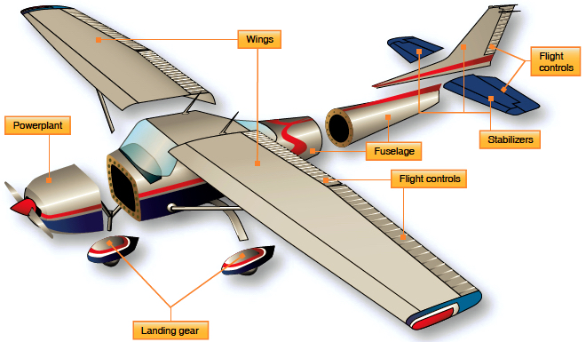
Every airplane breaks down into the same principal units.
| Unit | What it does |
|---|---|
| Fuselage | Main body. Carries crew, payload, and systems, and ties the wings, tail, and (often) landing gear together. |
| Wings | Make lift and carry it into the fuselage as bending, shear, and torsion. Often hold fuel and support engines and landing gear. |
| Empennage / stabilizers | Horizontal and vertical stabilizers give pitch and yaw stability and carry the elevators and rudder. |
| Flight controls | Primary: ailerons, elevator, rudder. Secondary: flaps, slats, spoilers, trim tabs. Hinge and actuator loads feed into spars and ribs. |
| Powerplant | Engines, mounts or pylons, and nacelles. Thrust, weight, and gyroscopic loads go through the mounts into the airframe. |
| Landing gear | Takes ground, braking, and side loads, which are some of the largest concentrated loads the structure sees. |
Semimonocoque fuselage
Skin and internal framework share the load.
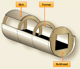
A monocoque (“single shell”) fuselage relies on the skin alone, like an egg or a can. It is efficient until it gets dented, and then it loses strength fast. Nearly all metal aircraft instead use semimonocoque construction. The skin carries a large share of the load (mainly shear and pressurization hoop tension), and an internal framework stiffens it and keeps it from buckling.
Parts of the shell
- Skin: riveted aluminum sheet. Carries shear, torsion, and cabin-pressure hoop stress. Forms the aerodynamic surface.
- Formers / frames: rings that set the cross-section shape and break the skin and stringers into short, buckle-resistant panels.
- Bulkheads: heavier frames at load points, such as wing and gear attachment, cockpit, and pressure boundaries. A pressure bulkhead closes the pressurized hull.
- Stringers: light, numerous longitudinal members (formed or extruded) that stiffen the skin and carry fuselage bending as axial tension and compression.
- Longerons: heavier longitudinal members, fewer in number, used where loads concentrate.
Why it works
Fuselage bending (tail loads, payload weight, landing) is carried mostly by the stringers and skin as tension on one side and compression on the other. Frames keep the compression side from buckling. Twisting from rudder loads and asymmetric gust loads is carried as shear flow around the closed skin. With so many redundant load paths, one cracked stringer or frame usually doesn't cause immediate failure. That is the basis of damage-tolerant design, and it's why small cracks have to be found and repaired.
Wing structure
A cantilever beam that also has to hold an airfoil shape.
Spars
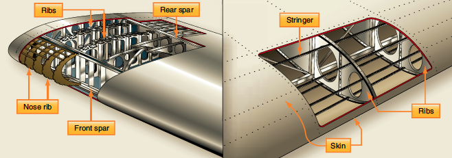
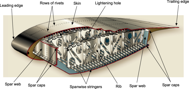
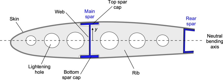
The main spanwise beams, running from the root to the tip. Most metal wings have a front (main) spar and a rear spar. Larger aircraft may add more. The spars carry most of the wing bending and vertical shear into the fuselage attachment.
Spar caps
The top and bottom flanges of the spar. They carry bending as axial load. In normal positive-g flight the top cap is in compression and the bottom cap is in tension. Putting them at the top and bottom of the airfoil, far from the neutral axis, gives the most bending stiffness for the weight.
Spar webs
The vertical plate joining the caps. It carries shear and holds the caps apart. Webs are often thin, so vertical stiffeners are added to stop them from shear-buckling.
Ribs
Chordwise members that give the wing its airfoil shape. They support the skin and stringers, carry air loads from the skin into the spars, and break the stringers into shorter, stronger columns. Heavier ribs are used at the root, at engine, gear, and flap fittings, and at fuel-tank ends.
Nose ribs
Short ribs ahead of the front spar that shape and support the curved leading-edge skin. They take the high local air pressure near the leading edge.
Stringers
Spanwise stiffeners riveted to the inside of the skin. They help carry bending, especially compression in the upper skin, and break the skin into small panels that resist buckling.
Skin
In a stressed-skin wing the skin is structure, not just a covering. With the spars and ribs it forms a closed torque box that carries twisting as shear flow, and the skin-stringer panels carry part of the bending.
Lightening holes
Holes cut where a web carries little load, to save weight. They are usually flanged (edge-formed), which stiffens the web against buckling so most of the lost strength comes back. They also make room for wiring, tubing, fuel flow, and access. Treat them as engineered features: you can't add, enlarge, or move one without engineering approval.
Spar construction types
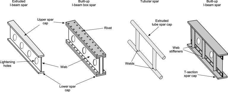
Different ways to build the same beam: caps far apart, joined by a web.
| Type | How it is built | Notes |
|---|---|---|
| Extruded I-beam | One extrusion with caps and web in a single piece, sometimes machined to taper. | Simple, with few fasteners. Common on smaller aircraft and secondary spars. |
| Built-up I-beam / box | Separate cap extrusions riveted to a sheet or plate web. Two webs make a box spar. | Thickness can change along the span. The riveted joints also stop cracks from running, which suits fail-safe design. |
| Tubular | Extruded tube caps joined by welded web members. | Mostly found on light aircraft and in truss-style structure. |
| Built-up with web stiffeners | Thin web with vertical stiffeners and T-section caps. | Stiffeners stop the thin web from shear-buckling, so the web can be lighter. Typical of transport-category wings. |
The FAA Airframe handbook also describes wood spars, truss spars, plate-web spars, sine-wave spars, and fail-safe spars with riveted webs.
The five stresses
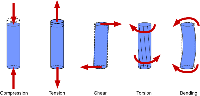
Tension, compression, shear, torsion, and bending. How each one shows up in the wing and fuselage.
| Stress | What it is | Where you see it |
|---|---|---|
| Tension | Pulling apart. The part tends to stretch. | Lower wing skin, stringers, and the bottom spar cap in flight. Pressurized fuselage skin (hoop and longitudinal tension). Tension is where fatigue cracks grow, which is why lower wing surfaces get close inspection. |
| Compression | Pushing together. The part tends to shorten or buckle. | Upper wing skin, stringers, and the top spar cap in flight. On the ground the wing hangs on its supports, and the upper side can go into tension while the lower side is compressed. Compression members usually fail by buckling, not crushing, so stringer and rib spacing matters. |
| Shear | Layers sliding past each other. | Spar webs carrying the wing's vertical load. Skin panels in a torque box. Rivets in a lap joint. Rivets are designed to be loaded mostly in shear. |
| Torsion | Twisting. It produces shear stress inside the material. | Wing twist from aerodynamic pitching moment, aileron and flap loads, and engines mounted ahead of the spar. Fuselage twist from rudder and asymmetric tail loads. Carried by the closed skin-and-spar box. |
| Bending | A mix of tension and compression across a section, with zero stress at the neutral axis. | Lift bends the wing upward: compression on top, tension on the bottom. The bending moment peaks at the root. The fuselage bends between the wing and the tail. Down-loads and ground conditions reverse the signs. |
Shop-floor takeaway
Scratches, tool marks, mis-drilled or elongated holes, and wrong-temper material all raise stress, and they do the most harm on tension-loaded parts like lower skins and bottom spar caps. That is where fatigue cracks start. Disposition goes through the SRM or engineering, never your own judgment.
Image credits & licenses
- Principal airframe units; skin/former/bulkhead; wing structure nomenclature: FAA Aviation Maintenance Technician Handbook – Airframe (FAA-H-8083-31B), Vol. 1, Ch. 1 “Aircraft Structures”, Figures 1-13, 1-16, 1-23. Federal Aviation Administration, U.S. government work, public domain.
- Stressed-skin wing cutaway: FAA artwork, public domain, as labeled in J. Gordon Leishman, Introduction to Aerospace Flight Vehicles, Ch. 10 “Aerospace Structures” (Embry-Riddle Aeronautical University, doi:10.15394/eaglepub.2022.1066).
- Wing spar section; spar types; five stresses: © J. Gordon Leishman / ERAU, J. Gordon Leishman, Introduction to Aerospace Flight Vehicles, Ch. 10 “Aerospace Structures” (Embry-Riddle Aeronautical University, doi:10.15394/eaglepub.2022.1066). CC BY-NC-ND 4.0. Shown unmodified, with attribution, for non-commercial educational use.
The page text is original general-aerospace summary written for this site. No Boeing, SRM, AMM, or E-3/E-6-specific data is reproduced.